ArduRover Autonomous Navigation using Semantic Segmentation

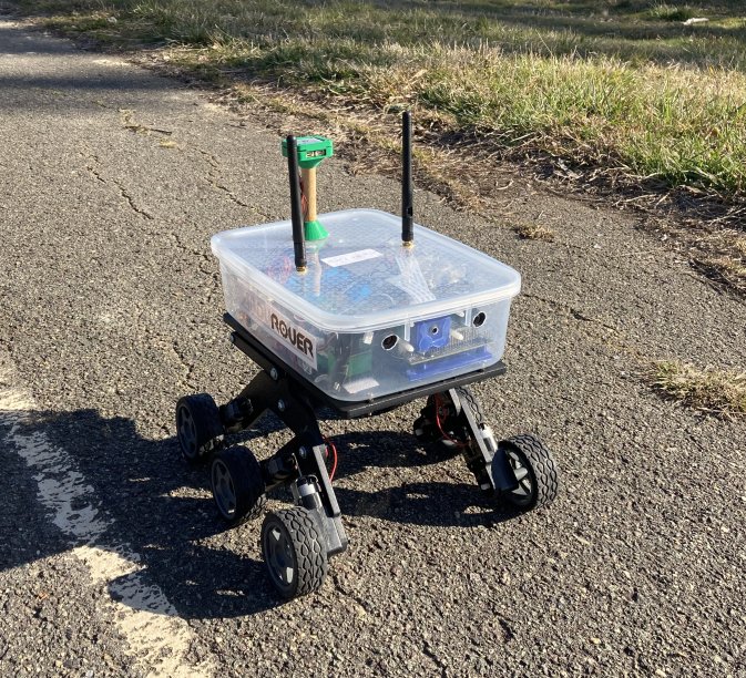
As an experiment in autonomous navigation with Ardupilot, I built a rover capable of autonomous path following.

It uses the ML/AI technique of semantic segmentation to determine where the desired path is, on a live video feed. Using this on a Jetson Nano, a relative bearing is generated to stay on the path. This bearing is sent to Ardupilot, which (in GUIDED mode) turns the rover to that bearing.

It’s a good example of using Companion Computer to do the vision processing and high-level planning, leaving Ardupilot with the lower level vehicle control

Hardware used

  • Bogie Runt Rover chassis
  • Roverbase power and motor controller board
  • Jetson Nano with Pi Camera V2
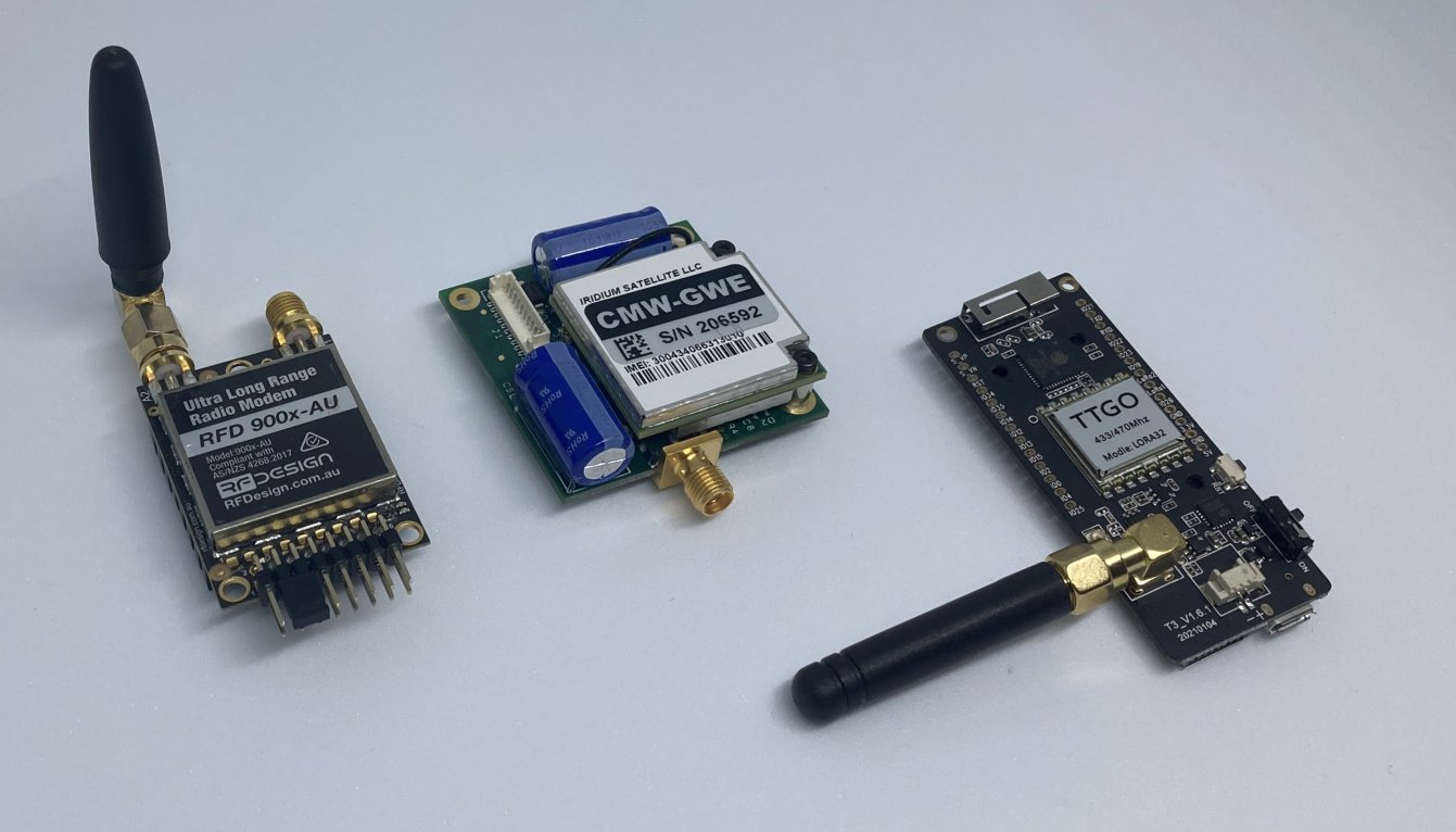
  • mRO X2.1-777 flight controller (any controller will generally work)
  • Ublox M8N GPS

The flight controller and Jetson were connected via UART, for MAVLink telemetry.

The layout is shown below:

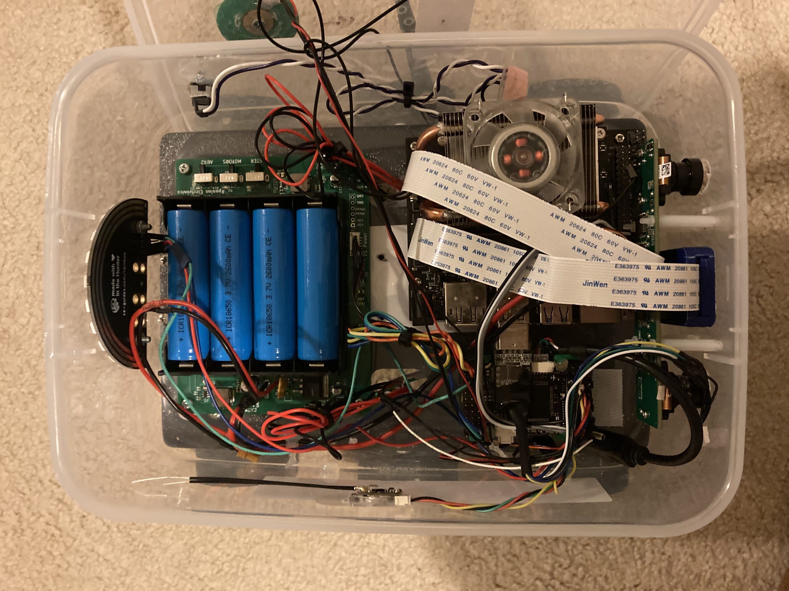
Note: A stereo camera was not fitted, but not used.

Software layout

All processing was done in realtime on the Jetson, which would sent out MAVLink messages (with desired speed and heading) to ArduPilot.

When ArduPilot was in GUIDED mode, it would move the rover as per the MAVLink messages.

The Rpanion-server software was used to manage telemetry streams, with the custom “segmav” software to process the video stream and output a desired heading and speed. Note the speed was hard-set at 0.5 m/s.

Segmav software

screenshot

The segmav software is designed to use Semantic Segmentation to determine the correct heading for a rover to stay on a road or path.

Segmav uses the following steps during processing:

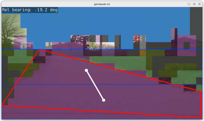
  1. Semantic segmentation is first used to separate the captured image into category areas: “Sky, Grass, Road, …”.
  2. The largest area (contour) with a “road” category (purple) is then found (red polygon).
  3. This contour is then split into two – halfway in the horizontal plane (blue boxes).
  4. The centroid of each half is calculated (white points).
  5. A line is drawn between the two points and the angle calculated (white line).
  6. The angle is put through a 3 point moving average to smooth out any large changes.
  7. This angle (yaw) is encoded into a MAVLink message SET_POSITION_TARGET_LOCAL_NED, in Body (relative) frame and the forward velocity and yaw components. The velocity component is hard-set to 0.5m/s.

The segmav source code is available from GitHub.

Performance

I could get 7fps using the fcn-resnet18-cityscapes-1024x512 dataset, with less than 300ms latency. This gave a low enough latency at speeds of 0.5m/s. For higher vehicle speeds, a faster Jetson (or smaller dataset) would be required.

A video demonstration is available below:

Issues

The accuracy was not great. The rover would occasionally dive off the path, due to an incorrect segmentation. A better tuned or larger dataset would likely reduce this from occurring.

The Runt Rover frame itself wasn’t good over grassy terrain. It would frequently get bogged when running over long grass.

Conclusions

This project is a good proof-of-concept for using semantic segmentation based navigation for following paths or tracks. Better datasets and a more powerful Jetson could

Rpanion-Server 0.9 Released

Version 0.9.0 of Rpanion-server has been released!

Rpanion-Server is an Open-Source software package for a managing the companion computer (such as the Raspberry Pi) connected to an ArduPilot-based flight controller.

Rpanion-Server consists of a node.js-based webserver for the user interface and mavlink-router for routing MAVLink telemetry from a connected flight controller. There are also modules for managing network connections, NTRIP streaming, flight log management, video streaming and viewing hardware information.

Version 0.9.0 adds the following major new features:

  • Automated uploading of flight logs
  • VPN support (Zerotier and Wireguard)
  • Automated generation of KMZ files from flight logs
  • Timestamp overlay for video streams
  • Various bugfixes and ease-of-use changes to the GUI

The documentation and pre-built disk images for the Raspberry Pi are available here.

The source code can be found here, at GitHub.

Bug reports and Pull Requests are most welcome.

Configuring Telemetry Rates in Ardupilot

This post is an explainer on the telemetry datarates in ArduPilot, plus information and data on how to configure the datarate to fit in lower-bandwidth radio systems.

Typical Datarates

Telemetry radios used in Ardupilot

All datarates in this article are averages and are rounded to 1 decimal place. Does not include actions such as downloading parameters or waypoints. All datarates are in the Vehicle → GCS direction.

ArduPilot telemetry is a series of MAVLink messages output from a UART (or serial) port on the flight controller.

The MAVLink messages may be a streamed message (message is emitted at some regular rate), such as the vehicle’s GPS position or hardware status. Other messages are emitted in response to a command or query from the ground station, such as downloading parameters or a confirmation of a flight mode change.

The following table shows the average datarate of the default streamed messages from the different ArduPilot firmwares at the default rate of 4Hz. Note the datarate whilst the vehicle is armed is slightly higher, as additional streamed messages (such as NAV_CONTROLLER_OUTPUT) are active. The datarate will vary depending on the vehicle hardware and configuration, as additional sensors (such as a 2nd GPS) will increase the datarate.

FirmwareDatarate when disarmedDatarate when armed
Plane3.5 kbytes/sec4 kbytes/sec
Copter3.5 kbytes/sec3.7 kbytes/sec
Rover3.4 kbytes/sec3.9 kbytes/sec

On a typical 57600 baud RF telemetry radio, this equates to 59%-69% of the available radio datarate being used.

Lowering the Datarate

If you are using a lower baud RF link, then ArduPilot’s streaming datarates may need to be trimmed down. There are several methods to do this.

The easiest method is to lower the rate of the streams. By default, a GCS will ask ArduPilot to stream at 4 Hz. This can be changed in Mission Planner in Config→Planner→Telemetry Rates or in MAVProxy via the --streamrate=n commandline option.

So, lowering the streamrates down to 1Hz gives the following average datarates:

FirmwareDatarate when disarmedDatarate when armed
Plane0.9 kbytes/sec1.0 kbytes/sec
Copter0.9 kbytes/sec0.9 kbytes/sec
Rover0.9 kbytes/sec1.0 kbytes/sec

Taking this further, streams can be disabled. For example, you may not want raw sensor readings or RC channel values. In that case, set the “Sensor” and “RC” streams to “0” in Mission Planner. At this time, MAVProxy does not support setting individual streamrates.

If preferred, these streamrates can be set on ArduPilot instead of the GCS 3.

The average datarates are now:

FirmwareDatarate when disarmedDatarate when armed
Plane0.7 kbytes/sec0.8 kbytes/sec
Copter0.6 kbytes/sec0.7 kbytes/sec
Rover0.6 kbytes/sec0.8 kbytes/sec

Individual Message Control

If finer grained control of which MAVLink messages are streamed is desired, the individual messages and rates can be controlled. There are a few methods for doing this.

For this example, a file containing the message ID’s and rate (in milliseconds) is placed in the SD card’s root directory:

message-intervals-chan0.txt

33 200
1 1000
74 2000

The above file tells ArduPilot that chan0 should stream

APSync

To assist users in getting up and running with their Pi-Connect boards, I’ve built a customised build of the APSync software. APSync is a web-based interface for managing an Ardupilot-based flight controller. It also includes low-latency videostreaming and a Wifi hotspot. It has been customised to include the Pi-Connect specific configuration for the Raspberry Pi (although it can be run without the Pi-Connect attached).

It’s easy to install – just go to the software page and download the APSync disk image. Load the image onto an SD card using an image writer and you’ll be good to go. No extra configuration required!